Sensing Light using LDR
A shopping List of Parts
- LDR: cost less than ₹10
- Resistor: 2.2KΩ , less than ₹1
- Capacitor: 300nF, costs less than less than ₹5
- Full size Breadboard: ₹ 80
- Jumper wires: Female to female, male to female
This work is only costs less than ₹100 if you are an electronic hobbyist. Since an electronic hobbyist have atleast the components like LDR, breadboard, jumper wires etc. on his hand.
For more information about the circuit and working of these programs visit our blog. Click here to our visit our blog.
LDR(Lght Dependent Resistor)
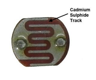
LDR is also known as Light Dependent Resistor or Photo Resistor or Photoconductive Cell or Photo Detector. The resistance of Photoconductive Cell decreases as the intensity of light increases. Photo Detectors are made up of semiconducting materials which possesses energy band equivalent to the order of that of photon. Cadmium Sulfide (CdS) is a potential candidate of photo detector whose Forbidden Energy Gap (FEG) ≅ energy of light. You can clearly see the CdS tracks on the top of LDR.
Circuit
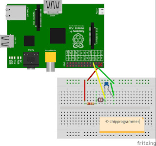
 |
| Circuit Diagram |
- Connect 3.3v Raspberry Pi pin(Pin 1) to positive rail of breadboard.
- Connect pin 6 of Raspberry Pi to negative rail of breadboard.
- Connect resistor, LDR and capacitor in series on terminal strip of breadboard as shown in figure.
- Connect broken (connectionless) end of resistor to positive rail of breadboard.
- Connect broken end of 330nF capacitor to negative rail of breadboard.
- The node joining to the LDR and 330nF capacitor to GPIO #4 using jumper wire. This diagram is created using an older version of Fritzing. That is why the Raspberry Pi model B (Rev 2) 26 pin version is shown in the image. But the program is working on both Raspberry Pi 2 and RPi3.
The Fritzing is an no-profit open source software that allows you to draw the breadboard, schematic, and PCB of a circuit. It is a very straight forward application and it has a wide range of graphical symbols.
If you have any doubt about about Raspberry Pi GPIO pins click here. In this blog chipprogrammer I used pin n for representing physical numbering of GPIO pins and GPIO #n to represent the BCM numbering of GPIO header where n is the number. However you should take care about numbering of GPIO. The above link will redirect to an interactive pin out of Raspberry Pi provided by Github.
Working Of Circuit
You can also use 5V GPIO hader for the working of circuit. Here I am using 3.3V GPIO header for protecting the GPIO pins. The 2.2 KΩ resistor is also used for protecting the GPIO pins. Here we are connecting LDR for sensing the light. As I mensioned earlier the LDR is a variable resistor and when light increaes the resistance will decrease. If you are using a flash light to check the working of circuit you may able to see the RC time constant of the circuit approaches zero gradually. If you were used 5V GPIO header as your Vcc your GPIO pins may get damaged. Since your GPIO pins can only tolerate 3.3V, since it is working on 3.3V CMOS logic.
In the world of electronics or electrical engineering there is only two outputs: analog or digital. As we all know that the change in resistance with respect to change in intensity of light is a an analog value. But the Raspberry Pi has no inbuilt or on-chip analog-to-digital converter(ADC). We can overcome this problem using the 330nF capacitor. You may interested to know how that is possible? The analog I/O with Raspberry Pi is little trickier. When we talk about voltages and Raspberry Pi, the voltages less than 1.8V is considered off and voltages greater than 1.8V is considered as on. It is shown on the figure below.
 |
| Analog I/O of Raspberry Pi(courtesy Raspberry Pi learning) |
The capacitor is just like your pocket and it wiill fill rapidly, if your time is good and it will become empty, if your fate and time is bad. It will charge faster if the variable resistance of LDR is lower due to the RC time constant is low. Also it will charge like a snail when the RC time constant is high at dark due to resistance of LDR become high. The time constant is given by: て=RC
For LDR, resistance at dark is approximately 1㏁ and hence for this resistance and 330nF capacitance て= 330 msec. For LDR, resistance at light is 10㏀ and hence て=33msec. You can calculate this resistance using online time constant calculator provided by digikey
The time module of the Python makes the program trickier and will help us to measure this time constants.
There is two methods to find out the light levels received by LDR. The first method is some complicated and in this method the Python time and RCtime of RPi.GPIO module is directly used for this program. The first program is abstracted in the gpiozero library and hence it easy to handle second program.
Method 1
ldr_spy.py
import RPi.GPIO as GPIO, time

# Tell the GPIO library to use
# Broadcom GPIO references
GPIO.setmode(GPIO.BCM)

# Define function to measure charge time
def RCtime (PiPin):
  measurement = 0
  # Discharge capacitor
  GPIO.setup(PiPin, GPIO.OUT)
  GPIO.output(PiPin, GPIO.LOW)
  time.sleep(0.1)

  GPIO.setup(PiPin, GPIO.IN)
  # Count loops until voltage across
  # capacitor reads high on GPIO
  while (GPIO.input(PiPin) == GPIO.LOW):
    measurement += 1

  return measurement

# Main program loop
while True:
    print (RCtime(4)) # Measure timing using GPIO4
This program is available on our github repository and it is named as ldr_spy.py. Cloning of these programs are discussed at the end of this session.
Method 2
ldr_RC_time_check.py
from gpiozero import LightSensor, Buzzer

  ldr = LightSensor(4)  # alter if using a different pin
  while True:
      print(ldr.value)
The program shown in method 2 is named as ldr_RC_time_check.py in our GitHub repository. You have to run these Python codes and observe the outputs using following commands:
$sudo python ldr_spy.py
$sudo Python ldr_RC_time_check.py
Immortal Brightness
You have to note down the values of these RC time constants during the dark and bright circumstances. These values will help you to turn on and off light by comparing real world situation. However I am not writing these programs to turn on and off light. You can change values in the RCtime((4)) in the if and else statements of the Python code corresponding to our GitHub repository named as newldr.py. Also you can change ldr.value in the if and eligible statements of our program (ldrorg.py) from GitHub repository to turning your LED on at night.
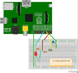
 |
| Circuit for turn on LED at dark |
The circuit diagram to turn on LED at night is shown above. There is no change in the above circuitry. In this circuitry we connected LED to the GPIO #17 through a 220Ω series resistor. The newldr.py is created in accordance with method 1 and ldrorg.py is created accordance with method 2.
newldr.py
import RPi.GPIO as GPIO, time

# Tell the GPIO library to use
# Broadcom GPIO references
GPIO.setmode(GPIO.BCM)

# Define function to measure charge time
def RCtime (PiPin):
  measurement = 0
  # Discharge capacitor
  GPIO.setup(PiPin, GPIO.OUT)
  GPIO.output(PiPin, GPIO.LOW)
  time.sleep(0.1)

  GPIO.setup(PiPin, GPIO.IN)
  # Count loops until voltage across
  # capacitor reads high on GPIO
  while (GPIO.input(PiPin) == GPIO.LOW):
    measurement += 1

  return measurement

# Main program loop
while True:
    print (RCtime(4)) # Measure timing using GPIO4
    GPIO.setmode(GPIO.BCM)
    GPIO.setup(17,GPIO.OUT)
    if RCtime(7)<600:
        GPIO.output(17,False)
    elif RCtime(7)>2200:
        GPIO.output(17,True)
ldrorg.py
import RPi.GPIO as GPIO
from gpiozero import LightSensor, Buzzer
ldr = LightSensor(4)  # alter if using a different pin
while True:
    print(ldr.value)
    GPIO.setmode(GPIO.BCM)
    GPIO.setup(17,GPIO.OUT)
    if ldr.value>0.5438098907470703:
        GPIO.output(17,False)
    elif ldr.value==0.0:
        GPIO.output(17,True)
Click here to visit our github repository for clone or download these codes. Alternatively you can also clone the code directly using following commands:
$cd ~
$git clone git://github.com/chipprogrammers/ldr.git
# you can navigate to our direcory cloned by you using this command and run Python scripts using sudo python command:
$cd ldr

 Hai friends. My name is Arun K Soman. I am from India. Now I am pursuing M.Sc. Electronics science degree from Cochin University of Science and Technoloy(CUSAT). I completed B.Sc Electronics from BPC college, Piravom. I am not a webdesigner. But I intersted in webdesigning. I have also some enthusiam in Electronics. I know how to use CSS kits like Bootstrap, w3.css etc. and HTML as well as Jekyll. This is not my first Jekyll template. I also created some jekyll templates before, But this is a full fledged one. This theme made with doing some tweaks on w3.css. It is fully open source under MIT Licence.Pull requests are welcomed to improve this theme.